

I took my first physics course this fall — college-level, calculus-based Physics I. The popular opinion seems to be that physics is intricate and Gordian. On the contrary, physics is onerously simple.
Most of the scientific revolution rests on a single concept: reducing the variables. If I had a dime for every frictionless surface, massless pulley, and airless planet I’ve encountered this semester — I might only have thirty bucks, but that’s a lot of dimes.
Galileo argued that if you ignored friction and air resistance, all objects fell at the same speed under the influence of gravity. It was tough to prove with Renaissance technology, and he had to resort to philosophical arguments in addition to his experiments. That mixture of empirical evidence and reasoning set the tone for scientific discourse that still prevails today. Quantum mechanics is the most successful predictive theory in the history of the world, but it also drives us nuts because we can’t explain the reason it works.
Newton couldn’t reason why gravity worked, either. What fool would believe in a force that acted instantly with no medium over millions of kilometers? It just did. He thought it was absurd and said as much, but dang if it didn’t work.
Maybe that’s the most challenging thing about physics. The deeper you dig, the fewer reasons you find. With reasons, you can create a story. With a story, you can explain things people will remember and repeat. Stories are the most effective communication technology humanity has ever invented, but stories rely on reasons. George killed Gatsby because Daisy ran over Myrtle with Gatsby’s car because she knew Myrtle was Tom’s mistress and, after all, Tom had made Gatsby and Daisy drive home together to prove he wasn’t afraid of Gatsby, and of course, Gatsby wouldn’t rat on Daisy because he loved her…
But to what do we owe the macabre and dramatic buoyancy force that kept Gatsby afloat face-down in his own pool, surrounded by the opulence of his heroic efforts to win back something that never belonged to him? From whence comes the hydrostatic force of an ocean of tears against a wall of indifference (assuming the wall is perfectly vertical and of equal density throughout)?
Alas, physicists have discovered many things that are, but not why. That’s hard to get excited about. There’s no Church of Things That Are. No one’s going to join your political movement to measure things precisely.
But here we are, vaccinated, well-fed, and riding the misinformation superhighway to hell, all because some nerds like me just had to figure out what stuff was made of and what it did when you poked it (with a thin, uniform rod of negligible mass).
All that is to say, here’s my physics project. I’ve been working on it for months. 24 pages, around 3,000 words, 112 equations, and 4 illustrations.
It’s a Rube Goldberg machine, the essence of over-engineering, specifically designed to have as much what and as little why as possible. However, I learned as much working on this project in my bedroom as in the classroom or lab. Every little click and whir has to be accompanied by equations of motion, forces, energy, momentum, rotational dynamics, and pendulum motion (frictionless, of course).
I am not avowing it is all correct. Even my professor had doubts about the second phase, the pendulum-on-a-pulley. I ran it by another physicist friend, who also expressed concern about that part. Neither one offered a more refined approach or solution, so it stands. If you are a physics-minded person, perhaps you’ll leave my first scathing peer review, which would be an exciting milestone for me.
More likely, you’ll enjoy the cheeky introduction and the summary. Maybe you’ll dig a little deeper for fun. If you discover the true purpose of the universe and the meaning of life, please let us know in the comments. Your fan,
Jonathan Byrd
Jonathan Byrd
PHY-251-100.101A
Nov 19, 2024
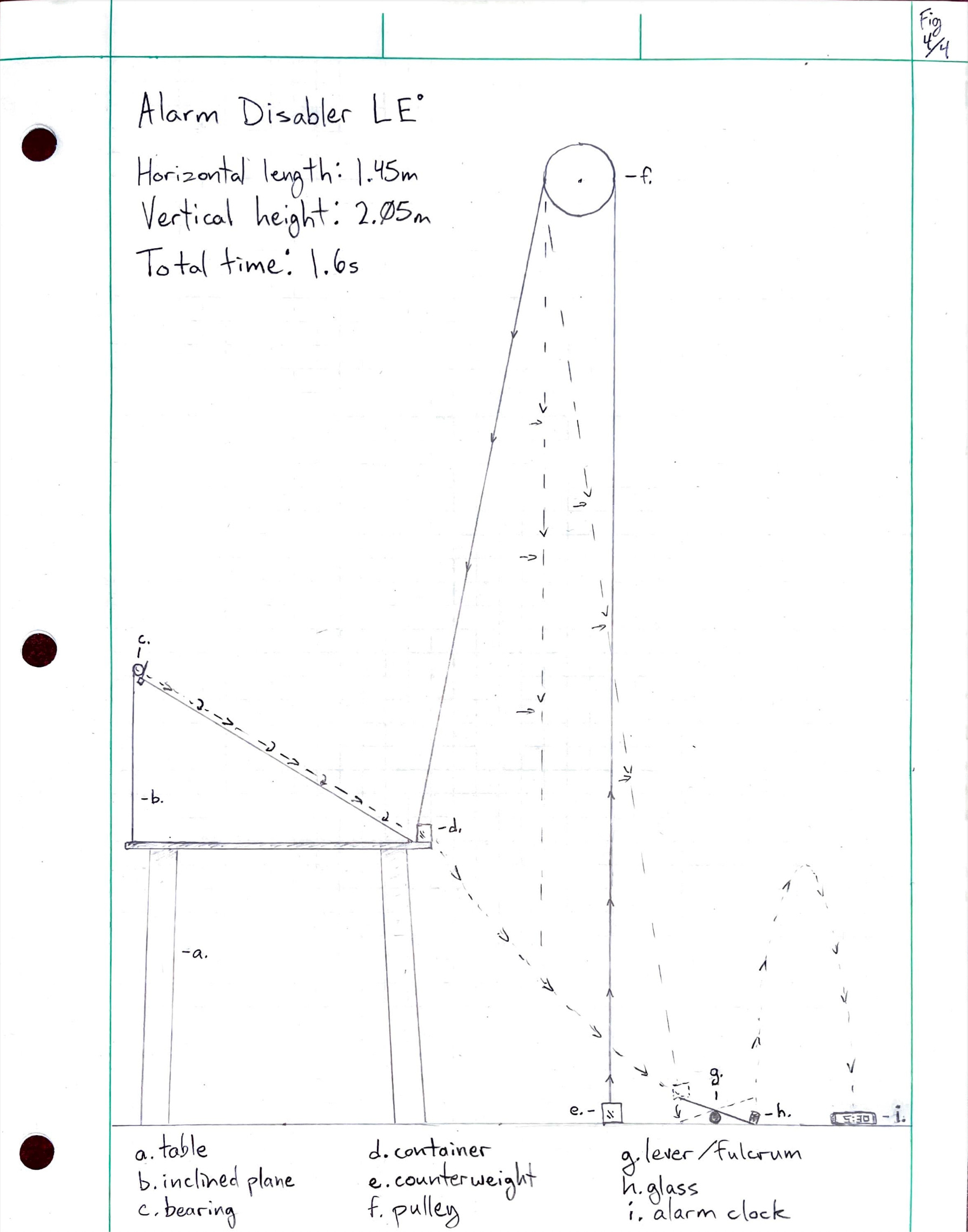
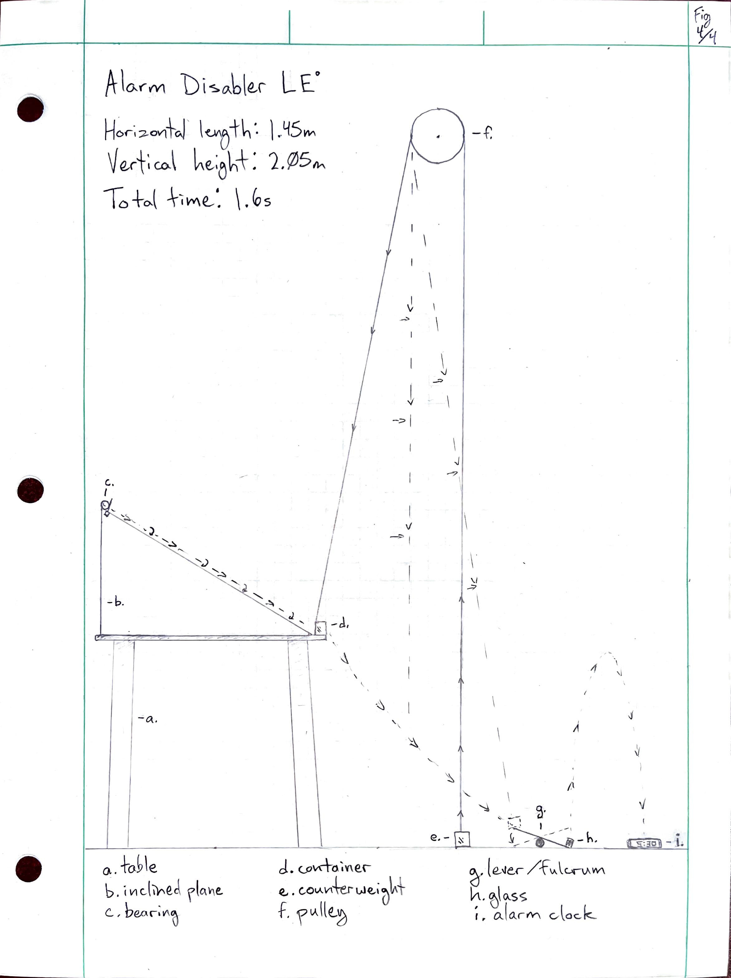
Rube Goldberg alarm disabler
Objective
I’m not a morning person. If I set my alarm clock too close to my bed, I can quickly turn it off and go back to sleep without realizing it. If I set my alarm clock far away, I must get up to turn it off. I was looking for a simple way to turn my alarm clock off from afar that would take enough time for me to fully awaken without having to get out of bed.
Beside my bed is a nightstand long enough for an inclined plane to give a large steel bearing the kinetic energy to enter a small open-sided container and knock it off the table. The container could easily be attached to a pulley with a small counterweight, allowing it to descend to the floor with enough momentum to push down on the high side of a lever. On the other side of the lever, I could place a small glass of water, and the torque of the lever would launch it across the room to land on the alarm clock. In case the water does not short the alarm clock, I will place a small chunk of sodium metal under the edge, which will ignite and light the fuse of an M-80 firecracker, which, according to the US Department of Energy, releases 22,990 Joules of energy upon detonation. This should be enough to destroy the alarm clock and transfer the momentum of the explosion into no less than two separate pieces. The momentum and trajectory of those pieces are beyond the scope of this experiment.
Materials
· 1 nightstand, stabilized with unread books
· 1 wooden inclined plane, a 30º-60º-90º right triangle such that its ramp is 30º from the horizontal and 0.7044m long. The height is 0.3522m, and the base is 0.61m.
· 1 butane lighter
· 1 cigarette paper
· 2 cm of Scotch tape
· 1 large steel bearing, .200kg, .038m in diameter.
· 1 small open-sided container, 0.1kg
· 1 counterweight, 0.25kg
· 1 frictionless pulley of negligible mass
· 1 massless string (free delivery from Amazon!)
· 1 wooden ruler to serve as a lever, .012kg, .31m in length.
· 1 prescription bottle to serve as a fulcrum, .03m diameter
· 1 small glass with water, .100kg
· 1 alarm clock
· 1 small chunk of sodium metal
· 1 M-80 firecracker
· 1 set of sound-dampening earmuffs
Procedure
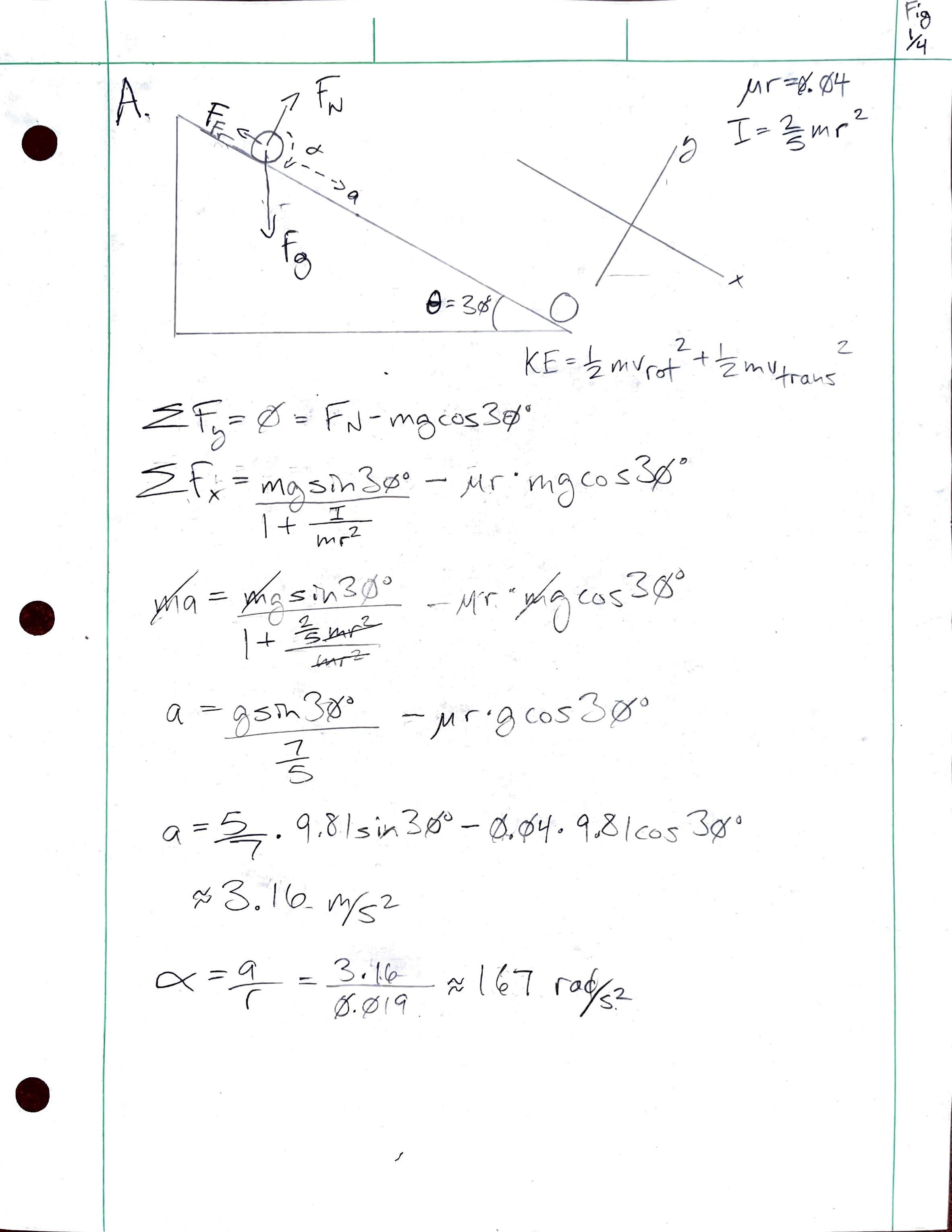
A. The Ramp (Fig.1/4)
Because the bearing needed to start from rest, as I do, I needed a dependable way to begin its descent with negligible force down the ramp upon waking to my alarm clock. I decided to tape a cigarette paper to stand vertically beneath the bearing as a gate. I could leave a small lighter on my nightstand beside the ramp and, upon waking, light the cigarette paper to release the bearing from rest.
Overcoming static friction:
To determine if the gravitational force is enough to overcome static friction between the wooden ramp and the bearing, I compared the gravitational force component acting along the inclined plane with the static friction force. The bearing’s mass is .0054 kg, the ramp is inclined at 30º from the horizontal, and the coefficient of static friction between steel and wood is approximately 0.4.
The 30º slope’s gravitational force component will overcome static friction and start the bearing rolling.
Rolling friction:
Once the bearing begins rolling, the only two forces we need to consider in calculating its motion to a reasonable degree are the gravitational force and rolling friction. Rolling friction is typically much lower than kinetic friction and very low for a hard sphere on a hard surface because of its minimal contact surface. Because friction is necessary to keep an object rolling rather than simply slipping down a plane, I assumed a coefficient of rolling friction of 0.04, an order of magnitude less than static friction. We can calculate and subtract the rolling friction force from the gravitational force along the slope.
We can see that even a tiny amount of rolling friction affects the net force within a range of two significant digits. Next, I wanted to know the translational acceleration, the final velocity, and the final angular velocity to accurately calculate the bearing's mechanical energy as it reached the bottom of the ramp. In addition, I calculated the time it took to reach the bottom of the ramp and the bearing's final momentum as it reached the table.
Translational acceleration:
To calculate the translation acceleration of the marble rolling without slipping down the inclined plane, I’ll use Newton’s second laws for translational and rotational motion (all translational motion in this system is in one dimension along the axis of the plane):
where T is torque, I is the moment of inertia, and alpha is angular acceleration. We know the friction force is responsible for the torque that causes the marble to roll rather than slip (as it would on a frictionless plane). We know that torque is also a cross-product of force and radius. Lastly, we know that all the force is being applied in the direction of rotation, so we can also say that:
so that
For a solid sphere rolling without slipping, the moment of inertia can be calculated using a triple integral, which is frankly beyond my current skill level, but the well-known equality is:
where M is the known mass of the marble, 0.2kg, and R is the known radius, 0.019m. Angular acceleration is related to linear acceleration through the equation
Plugging these relationships into :
We previously defined the marble’s translational acceleration, and now we can substitute our equality for the friction force and solve for the translational acceleration of our solid sphere in a rolling-without-slipping condition:
I then subtracted the acceleration of rolling friction by dividing its force by the bearing’s mass.
Rotational acceleration:
Final Velocity:
The final velocity of the bearing as it reaches the bottom of the ramp is:
Time to descend:
The time it takes to reach the bottom is:
Final angular velocity:
Rotational motion is related to translational motion through the equation
Final kinetic energy:
To calculate the total kinetic energy of the bearing as it reaches the bottom of the ramp, we must sum its translation and rotational kinetic energy.
I is the moment of inertia. The moment of inertia for a solid sphere is
Now, we can calculate the total kinetic energy of the bearing in the instant it reaches the table.
Final momentum:
The final momentum is
Impulse:
In this idealized situation, there is no change in momentum and J=0. We can show this is true by analyzing the impulse of the collision:
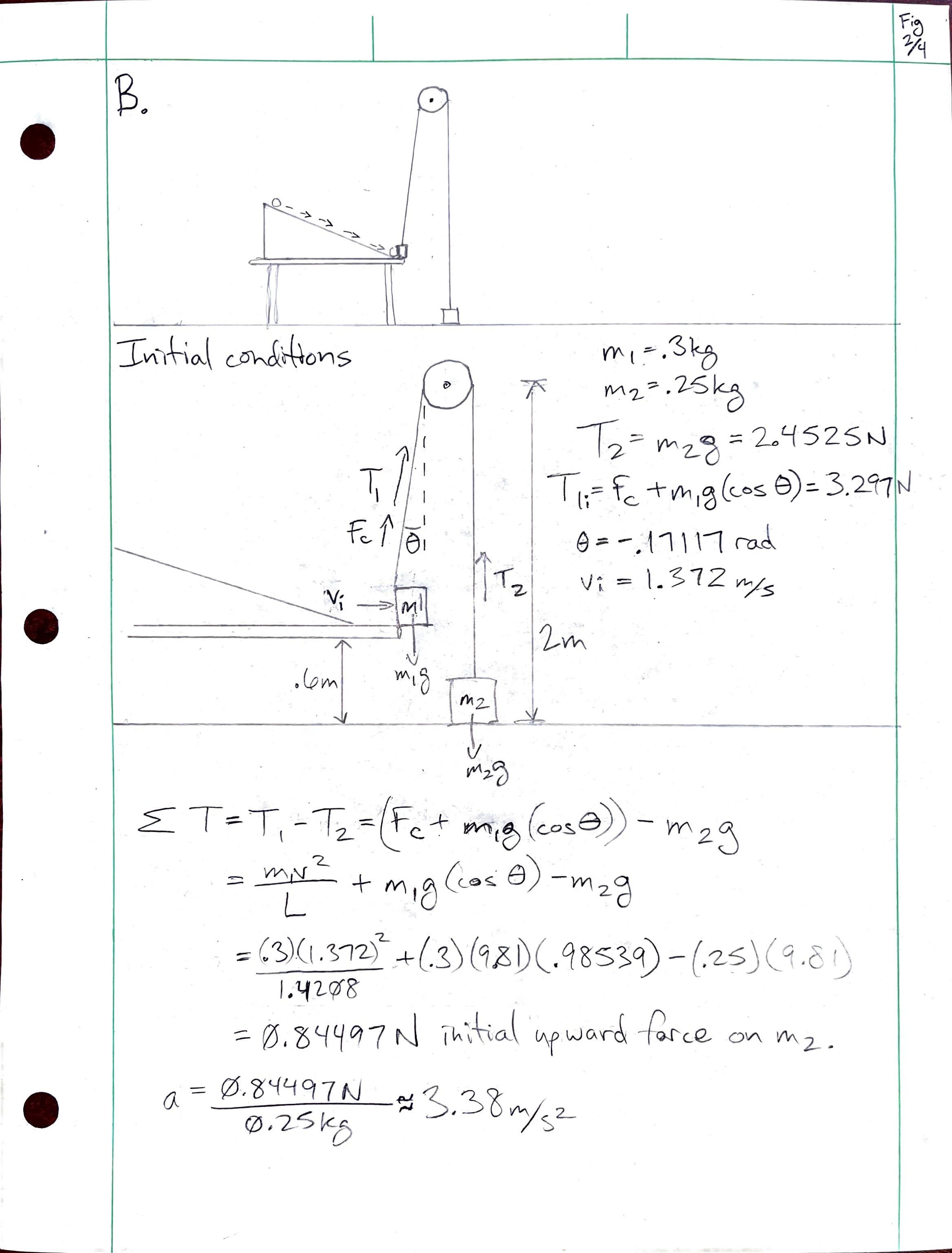
B. The Pulley (Fig. 2/4)
The first consideration in activating the pulley is whether the bearing has enough momentum to knock the container off the table's edge. We know the bearing’s momentum. Because the bearing, the table, and the container are rigid, and the distance between the bottom of the ramp and the container is small, we will consider the bearing’s dynamics to be conserved until it collides with the container.
The container has an open side for the bearing to enter and is held by a string of negligible mass by a small bar above the entrance side. When the container leaves the table, the weight of the bearing will tilt it so that it hangs at a 45º angle from the side where it is attached to the pulley, creating a diamond-shaped profile. The bearing may exhibit some stochastic dynamics once inside but will settle into the low side of the container and travel with it. Because of this setup, the collision can be considered approximately inelastic, and momentum is conserved.
The coefficient of static friction between the container and the table is 0.14, and the coefficient of kinetic friction is 0.12. The table is flat, so the normal force is simply mg, and the container’s mass is 0.1kg, making the total mass of the container/bearing system 0.3kg. The momentum must be enough to move the container and push it 0.03m across the wooden surface and off the table's edge.
I found the container/bearing system's initial velocity (in a frictionless case) by equating its momentum to the bearing's momentum.
Then, I determined the static friction force.
I then used the work-energy theorem to see if the force of the collision was enough to move the container. The energy is relatively easy to determine from the combined mass and initial velocity derived from the conservation of momentum.
The work done by the force of static friction to keep the system from moving is:
The kinetic energy must be at least equal to the work required to overcome the force of static friction and move the system an infinitesimal initial distance. I can ignore the cross-product and simply multiply because I am only concerned with one-dimensional motion along the x-axis.
The energy of the system will be far more than enough to overcome static friction. In fact, the system will have a significant velocity as it leaves the table. Effectively, there will be a combined pulley and pendulum system as the mass swings away. I calculated the work done by kinetic friction as the container moves 3cm and off the table's edge, subtracted it from the initial kinetic energy of the combined system, and solved for the velocity as the system leaves the table.
The pulley will be 1.4m above the table and .242m to the right horizontally. The string holding the container will form the hypotenuse of this right triangle, held taut by a .250kg counterweight on the floor. Its length and angle from vertical will be:
To find the component of the velocity along the direction of the pendulum arc, I took the first derivative of a circle function with L as the radius, .
The swinging mass will start in quadrant III at an angle of 0.17117 radians clockwise from the negative y-axis. I found its x-position to be:
I got the slope from the derivative of the circle function, took the arctan of the slope to an angle in radians, and then multiplied the horizontal velocity by the cosine of the angle to get the instantaneous linear velocity at that point in the pendulum’s arc:
Then, I used the linear velocity to work out the centripetal force, added gravity to the system, and found a close approximation of the initial tension on the string. I will henceforth refer to the bearing/container system as mass 1 and the counterweight as mass 2.
From there, I wondered how to approximate the condition of the entire pulley system as it evolved over time. I decided to use a massless and frictionless pulley and string (readily available on Etsy) so that I could focus on the complex pulley/pendulum dynamics of the falling mass.
Knowing the upward acceleration of mass 2, I could calculate the change in length of the string holding mass 1, which would affect the velocity of its pendulum motion. By adding the kinetic and potential energies of the initial condition and doing some algebra, I could relate the angular velocity to changes in the string's length. I needed the height of mass 1 above the lowest point at its current string length.
The table is .6m tall, and the pulley is 2m from the floor, so the vertical distance from the tabletop to the pulley is 1.4m. The initial string length is 1.4208m, so 0.0208m is a reasonable answer. I plugged this equation for height into my total energy function, then assumed maximum potential energy to find the maximum height of my swinging mass in the condition that the string length was unchanging. This told me whether the “small angle” formula for pendulum motion, generally best for maximum angles of 15º-20º, would help me approximate the motion of my system.
I could see that θmax would be more than the small-angle approximation of pendulum motion could handle, so I decided to approximate the system's motion stepwise using a quasi-Euler method. As I stepped forward by 0.01s increments, the upward acceleration of mass 2 would lengthen the string holding mass 1, which would change its angular velocity, which would, in turn, affect the tension force, which would affect the acceleration of the system, and so on. Initial conditions:
Step 1: Use the initial acceleration to find the change in string length.
Step 2: Use the initial angular acceleration to find the change in the pendulum angle.
Step 3: Use the initial angular acceleration to find the change in angular velocity.
Step 4: Use the new angular velocity and string length to update the tension force.
Step 5: Update the acceleration of the system.
Step 6: Build a spreadsheet to iterate this process in 0.01-second increments until mass 1 descends to step 3, the lever.
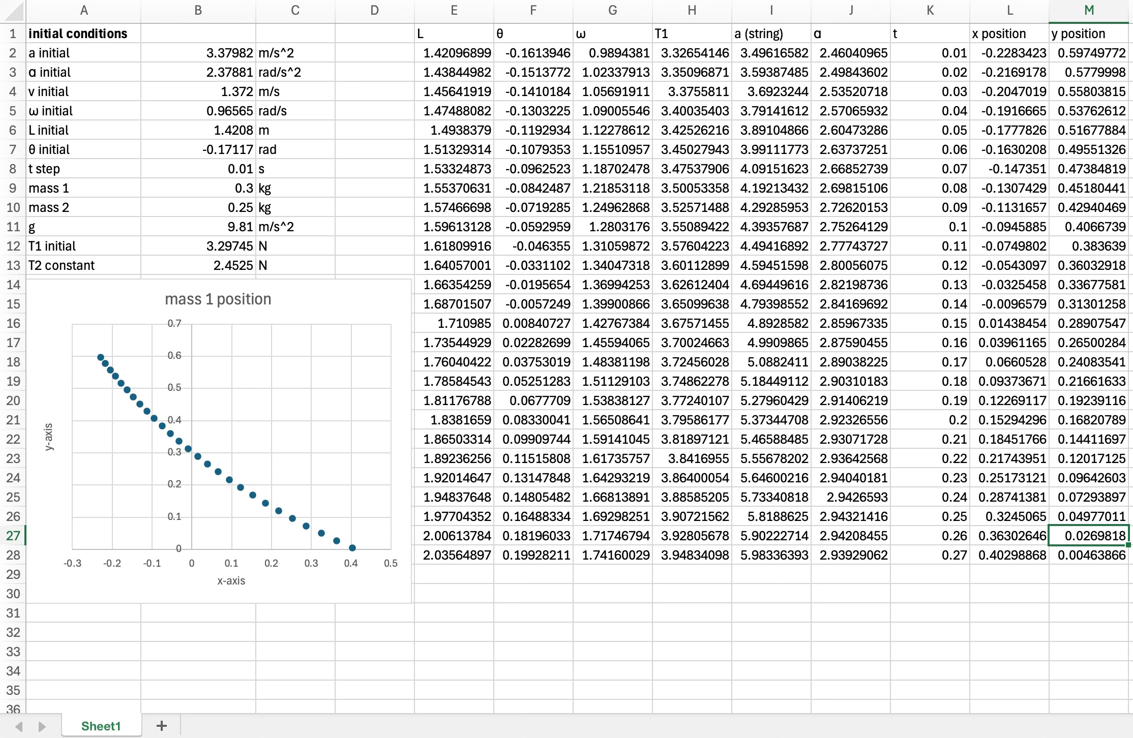
To test the model, I calculated the stepwise change in angular velocity using my previous total energy equation. It made a slight difference. That assured me that my original model was a good approximation. I kept the new angular velocity formula as my new Step 3, reasoning that the angle calculation increased the accuracy of the model:
I noticed that the acceleration of the pulley system continued to increase, even as it crossed the vertical when the effect of gravity should lessen as the angle again increased. At first, I thought I had made an error. I made another column in the spreadsheet that calculated only gravity's contribution, showing that gravity behaved as expected. I realized that the centripetal force due to the mass’s pendulum motion was increasing rapidly and overcompensating for the gravitational force, an enlightening example of centripetal force in action.
The model predicts that mass 1 will land on the end of a lever 6cm above the floor at approximately t=0.25s.
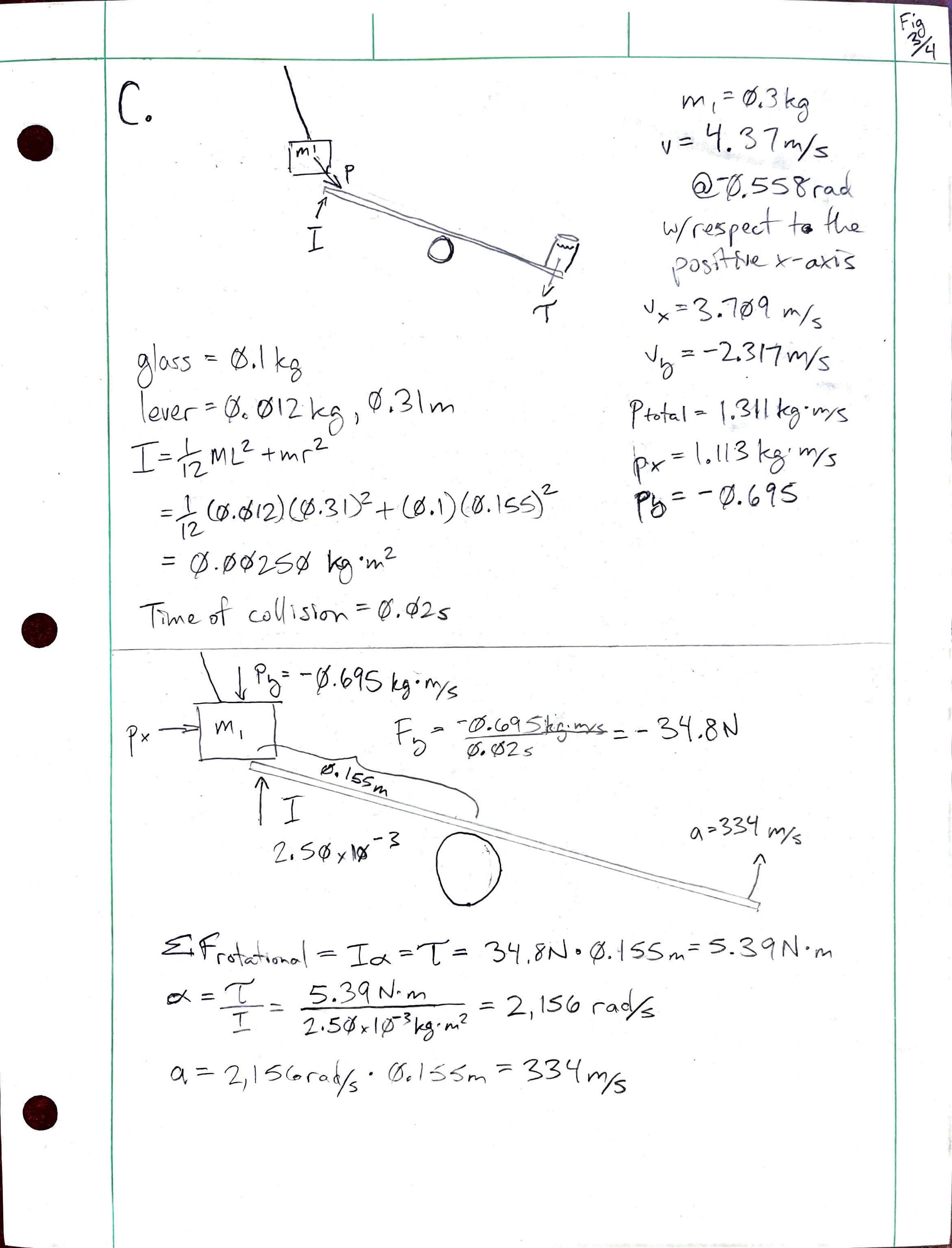
C: The Lever (Fig. 3/4)
Extrapolating from the swinging pulley model, mass 1 seems to hit the lever between t=0.24 and t=0.25. I calculated velocity and acceleration in the y-direction:
The lever will be a rigid ruler of negligible thickness. A glass of water with a mass of 0.1kg will sit on the lower end. Since the ruler is .31m, the distance from the center of mass to the glass of water is .155m. The moment of inertia for the lever and glass of water can be expressed as:
When the mass lands on the high end of the lever, both structures will travel together as the translational kinetic energy of the falling mass is converted into rotational kinetic energy in the mass/lever/glass system.
Unfortunately, this route led me to velocities that would send the glass through the roof. I wanted to avoid costly repairs while blowing up my alarm clock with an explosive, so I calculated impulse and force. A reasonable time for a rigid impact would be about .02s. If the mass slowed significantly in that time, the change in velocity in the y direction would be close to -2.31689m/s.
Using the impulse-momentum theorem, the average force F exerted over time t is:
The negative sign indicates that the lever/glass will briefly push up against the falling mass as the two objects collide. Therefore, the mass exerts the same force downward on the lever, which acts at a distance from the fulcrum to produce torque. I used the torque to find the lever's angular acceleration, which gave me linear acceleration that I could use to calculate the glass's trajectory.
This seems like an extraordinary amount of acceleration, but it will happen over a very short period. Since one side of the lever is accelerating at this rate, the low side with the glass must also be accelerating at the same rate. I knew that the friction of the glass against the ruler would be negligible under this amount of angular acceleration, so I assumed it would take about .01s for the glass to fly off the opposite end. With that in mind, I could find the angle of flight based on the resting angle of the lever, then use the linear acceleration to find the initial velocity and calculate the projectile motion of the glass of water. The glass’s projectile motion will begin a cm or so off the ground, and the alarm clock has a small height, but I think it’s safe to call both ends of the journey y=0.
So, I’ll need to put the clock's center about 20cm away from the lever. The maximum height of the glass’s parabola will be at t=½ of 0.679s, or .3395s.
The maximum height of the glass’s trajectory is a little more than 56cm.
The total length of the system is approximately 1.45m, which seems a little close to the bed, but that’s what the earmuffs are for. I’ll put them on before I light the cigarette paper to start the machine since the glass will land approximately 1.6 seconds after the bearing begins to roll (See Fig 4/4). Safety first!
Summary:
I had a blast on this project. It was a wonderful way to learn and practice these physics concepts, and the creative spirit kept me going when things got tough. If I survive the explosion, I’ll see you next semester in Physics II.
I applied concepts of 1-D motion, projectile motion, sliding with friction, pulleys, inclined planes, mechanical energy, collisions, momentum, rotational motion, rotational dynamics, and even some pendulum motion. Although I may have made it more challenging than necessary, my conceptual grasp of physics grew exponentially.
We barely discussed rolling without slipping in class. However, the machine's first step taught me a great deal about the power of even tiny amounts of friction. It also taught me to carefully distinguish between a system's translational and rotational motion and energy.
I could have glossed over the horizontal velocity of the pendulum mass or made it disappear somehow. However, the more I thought about it, the more interesting it became. I remembered dealing with drag force in the lab and tried to apply a similar stepwise method. It may not be exactly right, but it’s not far off, and hacking my way through the weeds of the problem was thrilling. Learning how to use Excel has honestly been one of the most significant benefits of this class. Thank you for taking a little extra time with me in that regard.
Okay, it’s time for bed. We’ll see how this thing works in the morning.
Just read thru your physics project. Saw that you had to learn Excell and thought you might be interested in knowing the guy that wrote Excell For Dummies is an old time musician (clawhammer banjo and guitar), music lover living in Tucson. I met John at Mt Airy Fiddle Festival years ago. He is a great guy! If you ever want/need a connection to the Excell expert let me know.
I chortled when I got to the M-80. Hope the new house survived the blast! 🧨